
NewsDetails
Assembly and Commissioning of Axial Balance Structure in High-Pressure Three-Screw Pumps
author:Tianyi Pump time:2026-06-24 16:22:19 Click:136
Assembly and Commissioning of Axial Balance Structure in High-Pressure Three-Screw Pumps
High-pressure three-screw pumps are widely used in marine fuel systems, hydraulic power units, lubrication systems, and industrial oil transfer applications. A key design feature ensuring stable operation under high pressure is the axial balance structure. This system is responsible for counteracting axial thrust generated during operation, maintaining rotor stability, reducing wear, and ensuring sealing reliability. Proper assembly and commissioning of this structure directly affect pump efficiency, vibration level, and service life.
Function of the Axial Balance System
During operation, fluid pressure acting on the screw surfaces generates significant axial force.
Without compensation, this force would push the rotor assembly toward one side, causing uneven wear and potential mechanical failure.
The axial balance structure is designed to neutralize or minimize this force through hydraulic balancing chambers, balance pistons, or pressure-equalizing grooves.
Axial balance is essential for maintaining rotor centering and preventing thrust-related damage in high-pressure screw pumps.
Key Components of Axial Balance Structure
The system typically includes:
Balance piston or balance sleeve
Pressure equalization chamber
Thrust bearing assembly
End cover sealing system
Axial clearance adjustment shims
Each component must be precisely machined and assembled to ensure correct force distribution.
Pre-Assembly Inspection Requirements
Before assembly, all components must be inspected for dimensional accuracy and surface quality.
Check rotor straightness, screw profile integrity, and housing bore concentricity.
Verify that sealing surfaces are free from scratches, corrosion, or deformation.
Any deviation in machining accuracy can significantly affect axial balance performance.
Step 1: Bearing and Shaft Assembly
Install thrust bearings and radial bearings according to specified orientation.
Ensure proper lubrication of bearing surfaces before installation.
Press-fit components should be installed using controlled force to avoid deformation.
Step 2: Installation of Rotor and Screw Assembly
Insert screw rotors into the housing carefully, avoiding contact with casing walls.
Maintain correct alignment between driving and driven screws.
Check smooth rotation by manual turning after installation.
Step 3: Installation of Axial Balance Components
Install balance piston or sleeve according to design orientation.
Ensure that pressure channels are not blocked and flow paths are clean.
Install sealing rings with correct compression to prevent internal leakage.
Correct positioning of balance components is critical for stable axial force compensation.
Step 4: Adjustment of Axial Clearance
Axial clearance must be adjusted using precision shims or adjusting screws.
Too large clearance results in internal leakage and pressure loss.
Too small clearance causes friction, overheating, and possible seizure.
Balance adjustment should achieve minimal friction with stable hydraulic sealing.
Step 5: End Cover and Seal Assembly
Install end covers evenly to avoid distortion of housing structure.
Tighten bolts in a cross pattern to ensure uniform stress distribution.
Verify that mechanical seals or packing systems are correctly installed and aligned.
Step 6: Manual Rotation and Resistance Check
After assembly, rotate the shaft manually to confirm smooth operation.
There should be no periodic resistance, scraping, or abnormal stiffness.
Any abnormal resistance indicates improper axial balance or misalignment.
Commissioning Procedure
Initial Low-Speed Operation
Start the pump at low speed to allow gradual hydraulic stabilization.
Monitor pressure, vibration, and temperature during initial operation.
Axial Force Verification
Check for abnormal axial vibration or end thrust movement.
Stable operation indicates correct balance performance.
Gradual Load Increase
Increase system pressure step by step while monitoring performance.
Ensure that axial load remains stable under full operating conditions.
Common Assembly Errors
Incorrect shim selection leading to improper clearance
Blocked pressure equalization channels
Improper bearing installation direction
Uneven bolt tightening causing housing deformation
Contamination inside balance chamber
Even minor assembly deviations can significantly affect axial stability under high pressure.
Troubleshooting During Commissioning
If abnormal noise or vibration occurs:
Check axial clearance and bearing condition
Inspect balance piston sealing integrity
Verify pressure channel continuity
Recheck rotor alignment and housing concentricity
Preventive Maintenance Recommendations
Regular inspection of axial clearance and bearing condition is essential.
Monitor vibration trends to detect early imbalance issues.
Maintain clean hydraulic oil to ensure proper pressure equalization performance.
Conclusion
The axial balance structure in high-pressure three-screw pumps is critical for controlling axial thrust, maintaining rotor stability, and ensuring reliable operation. Proper assembly requires precise alignment, correct clearance adjustment, and clean pressure channels. Commissioning must be carried out gradually under controlled conditions. Accurate axial balance assembly is the key factor in ensuring long-term stability and high-pressure performance of three-screw pump systems.
References
Pump Handbook, Fourth Edition, McGraw-Hill Education
Hydraulic Institute Standards for Screw Pumps
API Standards for Rotary Positive Displacement Pumps
Machinery Design and Axial Thrust Balance Engineering Manual
Industrial Pump Assembly and Commissioning Guidelines
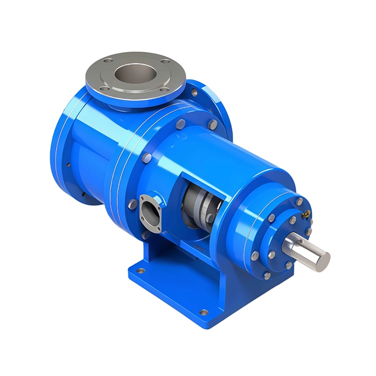
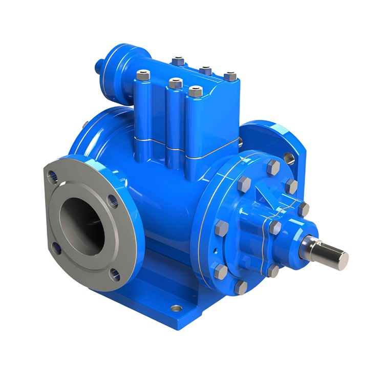
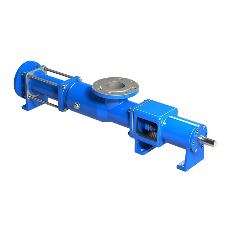
 Recommended Products
 Contact us
—— Contact:Mr. Shi
—— Tel:+86 15612730683
—— Email:btclyb@163.com
—— Url:https://www.tianyi-pump.com
—— Address:260 meters east of Xiaoquan Village Committee, Bozhen, Botou City, Cangzhou City, Hebei Province